The British Standard
This week’s diversion is related to plane standards. A few times the term “to British Standards” has been thrown around in the Vintage Tool Patch, but what does that really mean?
The British Standards Institution (BSI) was established in 1901 as the Engineering Standards Committee. The organization adopted the name British Standards Institution in 1931. Their charter was meant to:
- promote trade by developing common industrial standards
- reduce waste through simplifying production and distribution
- protect the consumer through licensed marks to identify products conforming to the standard
How does this apply to hand planes? Well in 1963 the BSI published the first edition of British Standard 3623:1963 titled “Specification for Woodworker’s metal-bodied planes”. If you’re feeling nostaligic, BSI offers a hard copy of the non-withdrawn standard for £192. There’s a tool collector advertising copies of the first edition plane standard for £15 as well, but it wouldn’t be from the source.
The standard has been revised and re-published several times. Here are the two most significant ones, BS 3623 and ISO 2726.
- BS 3623:1963 remains the original standard. It was 41 pages and had 24 figures illustrating typical designs of a variety of hand planes. It has since been withdrawn.
- ISO 2726:1973 became the first international standard based very much on the work done by BSI.
- BS 3623:1981 The original British Standard was revised in 1981 to use metric measurements instead of imperial.
- ISO 2726:1995 was a more recent release of the international standard totaling 6 pages. It has been since withdrawn.
- Individual countries have released clones of either the BS or ISO standards.
So what is in the “British Standard”?
- The nomenclature (see Figure 1 for sixteen plane parts: plane body, sole, clearance, handle, knob, frog, adjusting screw, adjusting nut, depth adjusting lever, lever cap assembly, lever cap lock, lateral adjusting lever, lever cap screw, mouth, plane cutter, and cap iron. It’s worth noting that per the standard the rear handle is a “handle”, and not a tote or toat.
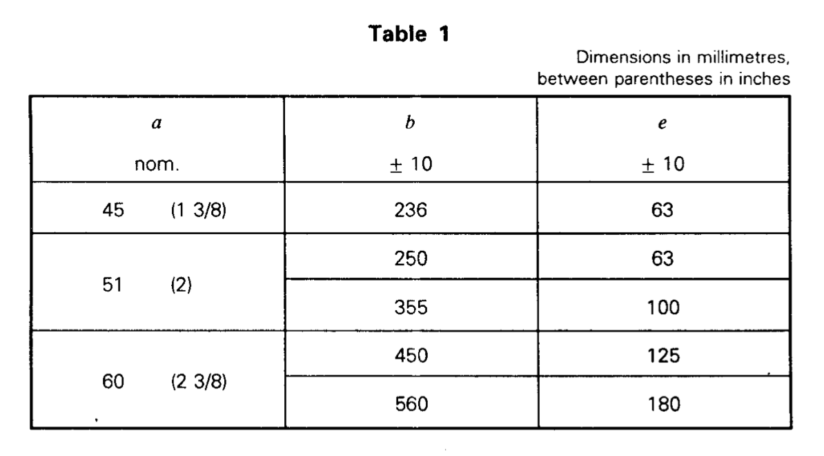
- Dimensions (see Figure 2 and Table 1). There is a tolerance of 10 millimeters in either direction for the length of a plane. The recognized standard widths are 45mm (1 3/8 in.), 51mm (2 in), and 60 mm (2 3/8 in.).
- Shape (see Figure 2). Basically a metal plane has to be shaped like what we all know is a plane.
- Material. Cast iron or steel for body, frog, and lever cap. Steel must be used for the lever cap screw and adjusting screw. Steel, brass, or plastic are suitable for the adjusting nut. Wood must be hardwood timber, straight-grained, and free from defects with a moisture content of 10% to 15%. Plastic may also used for the knob and handle so long as they are smoothly finished and have similar mechanical properties to wood.
- Sole. The working face should be finished smooth and ground flat with a tolerance of 0.04mm. Side faces should be within 30 seconds of a degree of perpendicular to the sole. The mouth shall be with 1 degree of perpendicular to the sides of the sole.
- Frog. The frog shall be firmly fixed on the sole to enable correct adjustment of the mouth aperture (called cleareance in the nomenclature).
- Lateral Adjusting lever. The lever shall be capable of positioning the cutting edge at an angle within 1 degree and 30 seconds relative to face of the sole.
- Adjusting Nut. Shall be knurled or special shape for grip, and impart a minimum of 3mm of movement to the cutter.
- Knob and handle. Must be smoothly finished and fixed firmly to the plane body.
- Protection. Exposed bright metal parts shall be given anti-corrosion treatment.
- Finish. All components of each plane shall be free of burrs, scale, flaws, and other defects. The un-machined surfaces (excluding the cutter and cap iron) shall be painted, lacquered, black-japaned, powder epoxy coated, nickel or nickel chrome plated.
When testing the standards, the quality control falls upon the manufacturer. Most likely, a ground flat rule and looking for light gaps would have been used by the person performing the QC of the sole’s flatness.
The End.
Figure 1
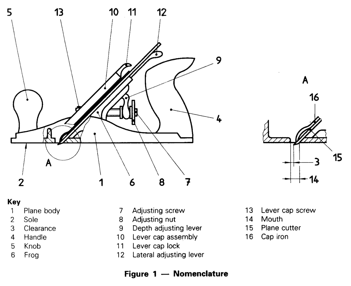
Figure 2
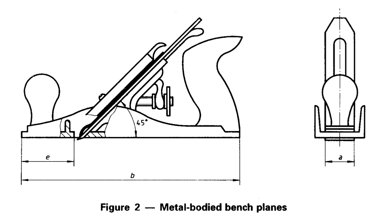
Table 1