Making a Blade Holder for a Record 043
The Record 043 is convenient, compact, and does its job grooving and cutting rebates remarkably well. So well that prices on complete models are going up. That said, they can still be found for a decent price if you’re willing to put in a bit of work.
One of the most commonly missing pieces on the 043 is the blade holder. Without one, the plane doesn’t function. On December 29th I found an 043 for £16.49 (including shipping) that was called a “parts plane” because it was missing its depth stop, blade holder, and irons. With the fence, rods, body, fence screws and depth stop screw in place, it only needed a depth stop, blade holder, and cutters to be complete again. I’ve got a spare depth stop i made from previous adventures, so off to making a blade holder.
For materials you need 3/4” x 1/4” flat stock, 3/8” or 1/2” drill rod, and a thumbscrew. The hardware store didn’t have any thumbscrews so I picked up a wing nut and 1-1/2” machine screw.
For tools I used a hacksaw, file, sandpaper, torch, flux, and silver solder.
I realize not everyone has silver solder. That’s okay! You can use JB Weld, too. The key takeaway is just be sure to epoxy both the joint and add another quarter inch of epoxy on the left cheek (the side that faces away from the plane) to help with holding power. Why is that? The 1/8 square inch of contact area with silver solder will hold about 5,000 pounds of force. A quarter inch of contact area with JB Weld will hold about 750 pounds of force. Even if you over tighten the thumb screw to the max by hand (there’s no need to do this), you shouldn’t be putting more than 500 pounds of force into the holder. No need to go crazy with the JB Weld, but giving yourself a little more surface area along the left side will give penty of buffer. Make sure to prepare the surfaces appropriately by sanding with 220 grit, and then clean with acetone or alcohol before using epoxy.
My process is explained with pictures below.
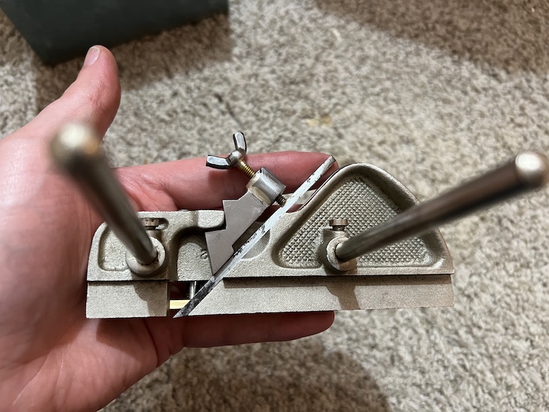
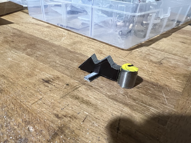
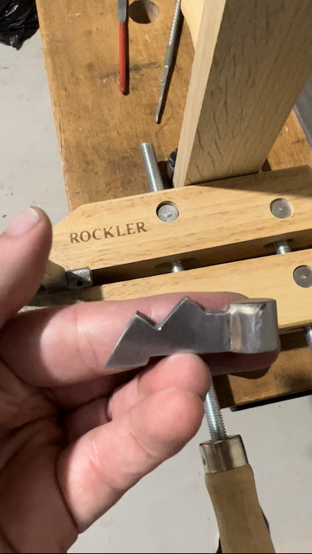
The Final Product
The test fit of my fence and blade holder on another Record 043 with a 1/8” wide iron. Now that I look at it, an all brass thumbscrew might look better.
Layout and Sawing
Sharpie layout and saw close to the lines.
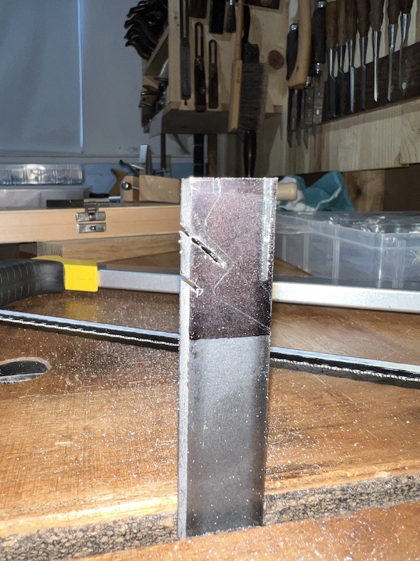
More Sawing
Lots of sawing, but the more you saw the less you file.
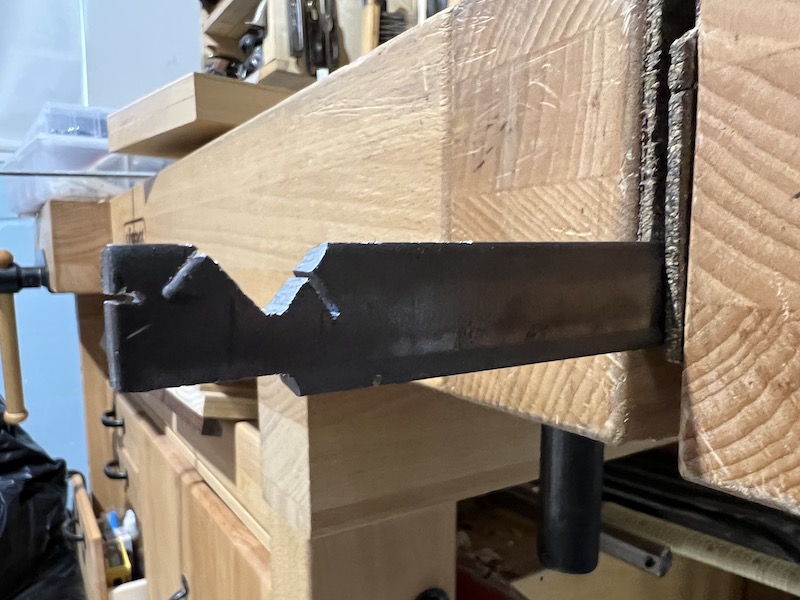
Rough Cut Parts
Here’s where I’m at after the work with the hacksaw.
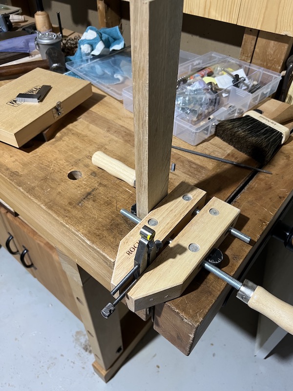
Filing
To file at all different angles, I did some creative clamping. A rat tail file to create a curve for the drill rod to rest.
Here’s where we’re at with fit. For silver solder you want a visible

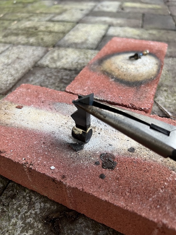
Silver Soldering
All soldered up. You can see the blade holder and screw. A little silver solder goes a long way. Your flux does all the work. I used high-temp black flux because it’s really easy to overheat these tiny parts.
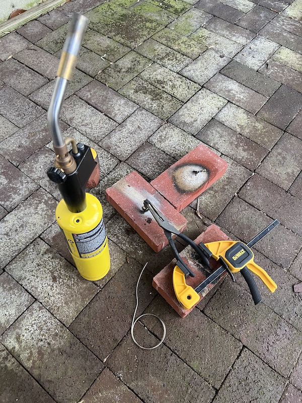
Just gravity, pliers, and a clamp for holding.
More Filing
After some filing to bring it down to final dimensions.
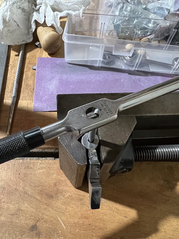
Tapping for the Thumb Screw
The back is tapped #8-32. If I were to do this again, old move the hole slightly to the left in this image.
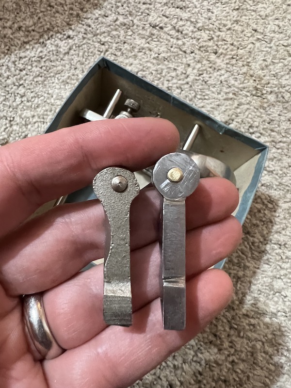
Comparing to the Original
The side-by-side with an original part looks pretty good! We’re a hair longer, but that won’t matter.
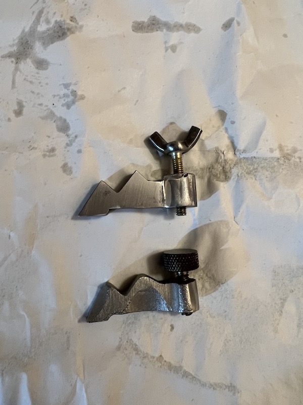
A hair less wide, but this should be even less fragile that the cast original.
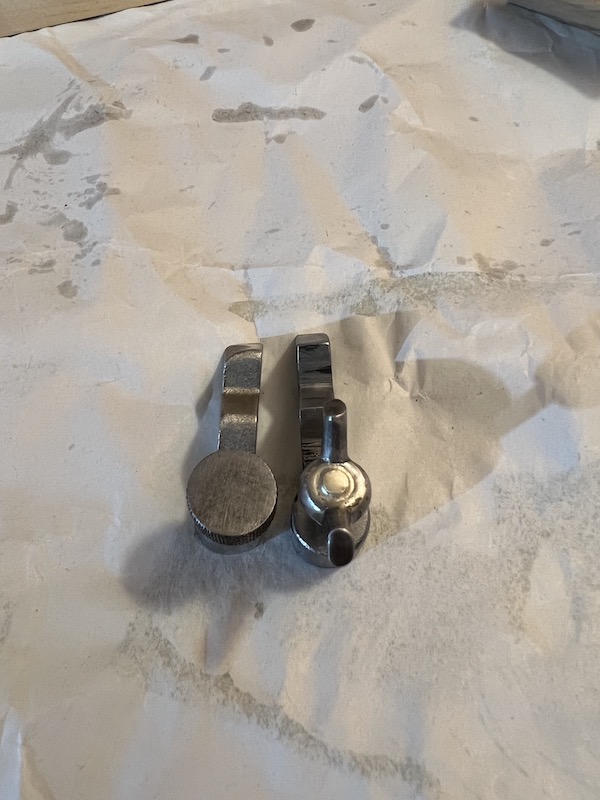
Note the screw placement. The original is slightly more to the right, but this works.